Fields are the basic building block for family symbols. The mechanisms for building up from fields to the root instruction symbol are the constructor and table.
A constructor is the unit of syntax for building new symbols. In essence a constructor describes how to build a new family symbol, by describing, in turn, how to build a new display meaning, how to build a new semantic meaning, and how encodings map to these new meanings. A table is a set of one or more constructors and is the final step in creating a new family symbol identifier associated with the pieces defined by constructors. The name of the table is this new identifier, and it is this identifier which can be used in the syntax for subsequent constructors.
The difference between a constructor and table is slightly confusing at first. In short, the syntactical elements described in this chapter, for combining existing symbols into new symbols, are all used to describe a single constructor. Specifications for multiple constructors are combined to describe a single table. Since many tables are built with only one constructor, it is natural and correct to think of a constructor as a kind of table in and of itself. But it is only the table that has an actual family symbol identifier associated with it. Most of this chapter is devoted to describing how to define a single constructor. The issues involved in combining multiple constructors into a single table are addressed in Section 7.8, “Tables”.
A single complex statement in the specification file describes a constructor. This statement is always made up of five distinct sections that are listed below in the order in which the must occur.
- Table Header
- Display Section
- Bit Pattern Sections
- Disassembly Actions Section
- Semantics Actions Section
The full set of rules for correctly writing each section is long and involved, but for any given constructor in a real specification file, the syntax typically fits on a single line. We describe each section in turn.
Every constructor must be part of a table, which is the element with an actual family symbol identifier associated with it. So each constructor starts with the identifier of the table it belongs to followed by a colon ‘:’.
mode1: ...
The above line starts the definition of a constructor that is part of the table identified as mode1. If the identifier has not appeared before, a new table is created. If other constructors have used the identifier, the new constructor becomes an additional part of that same table. A constructor in the root instruction table is defined by omitting the identifier.
: ...
The identifier instruction is actually reserved for the root table, but should not be used in the table header as the SLEIGH parser uses the blank identifier to help distinguish assembly mnemonics from operands (see Section 7.3.1, “Mnemonic”).
The display section consists of all characters after the table header ‘:’ up to the SLEIGH keyword is. The section’s primary purpose is to assign disassembly display meaning to the constructor. The section’s secondary purpose is to define local identifiers for the pieces out of which the constructor is being built. Characters in the display section are treated as literals with the following exceptions.
-
Legal identifiers are not treated literally unless
- The identifier is surrounded by double quotes.
- The identifier is considered a mnemonic (see below).
- The character ‘^’ has special meaning.
- White space is trimmed from the beginning and end of the section.
- Other sequences of white space characters are condensed into a single space.
In particular, all punctuation except ‘^’ loses its special meaning. Those identifiers that are not treated as literals are considered to be new, initially undefined, family symbols. We refer to these new symbols as the operands of the constructor. And for root constructors, these operands frequently correspond to the natural assembly operands. Thinking of it as a family symbol, the constructor’s display meaning becomes the string of literals itself, with each identifier replaced with the display meaning of the symbol corresponding to that identifier.
mode1: ( op1 ),op2 is ...
In the above example, a constructor for table mode1 is being built out of two pieces, symbol op1 and symbol op2. The characters ‘(‘, ’)’, and ‘,’ become literal parts of the disassembly display for symbol mode1. After the display strings for op1 and op2 are found, they are inserted into the string of literals, forming the constructor’s display string. The white space characters surrounding the op1 identifier are preserved as part of this string.
The identifiers op1 and op2 are local to the constructor and can mask global symbols with the same names. The symbols will (must) be defined in the following sections, but only their identifiers are established in the display section.
If the constructor is part of the root instruction table, the first string of characters in the display section that does not contain white space is treated as the literal mnemonic of the instruction and is not considered a local symbol identifier even if it is legal.
:and (var1) is ...
In the above example, the string “var1” is treated as a symbol identifier, but the string “and” is considered to be the mnemonic of the instruction.
There is nothing that special about the mnemonic. As far as the display meaning of the constructor is concerned, it is just a sequence of literal characters. Although the current parser does not concern itself with this, the mnemonic of any assembly language instruction in general is used to guarantee the uniqueness of the assembly representation. It is conceivable that a forward engineering engine built on SLEIGH would place additional requirements on the mnemonic to assure uniqueness, but for reverse engineering applications there is no such requirement.
The ‘^’ character in the display section is used to separate identifiers from other characters where there shouldn’t be white space in the disassembly display. This can be used in any manner but is usually used to attach display characters from a local symbol to the literal characters of the mnemonic.
:bra^cc op1,op2 is ...
In the above example, “bra” is treated as literal characters in the resulting display string followed immediately, with no intervening spaces, by the display string of the local symbol cc. Thus the whole constructor actually has three operands, denoted by the three identifiers cc, op1, and op2.
If the ‘^’ is used as the first (non-whitespace) character in the display section of a base constructor, this inhibits the first identifier in the display from being considered the mnemonic, as described in Section 7.3.1, “Mnemonic”. This allows specification of less common situations, where the first part of the mnemonic, rather than perhaps a later part, needs to be considered as an operand. An initial ‘^’ character can also facilitate certain recursive constructions.
Syntactically, this section comes between the keyword is and the delimiter for the following section, either an ‘{‘ or an ‘[‘. The bit pattern section describes a constructor’s pattern, the subset of possible instruction encodings that the designer wants to match the constructor being defined.
The patterns required for processor specifications can almost always be described as a mask and value pair. Given a specific instruction encoding, we can decide if the encoding matches our pattern by looking at just the bits specified by the mask and seeing if they match a specific value. The fields, as defined in Section 6.1, “Defining Tokens and Fields”, typically give us our masks. So to construct a pattern, we can simply require that the field take on a specific value, as in the example below.
:halt is opcode=0x15 { ...
Assuming the symbol opcode was defined as a field, this says that a root constructor with mnemonic “halt” matches any instruction where the bits defining this field have the value 0x15. The equation “opcode=0x15” is called a constraint.
The standard bit encoding of the integer is used when restricting the value of a field. This encoding is used even if an attach statement has assigned a different meaning to the field. The alternate meaning does not apply within the pattern. This can be slightly confusing, particularly in the case of an attach values statement, which provides an alternate integer interpretation of the field.
More complicated patterns are built out of logical operators. The meaning of these are fairly straightforward. We can force two or more constraints to be true at the same time, a logical and ‘&’, or we can require that either one constraint or another must be true, a logical or ‘|’. By using these with constraints and parentheses for grouping, arbitrarily complicated patterns can be constructed.
:nop is (opcode=0 & mode=0) | (opcode=15) { ...
Of the two operators, the logical and is much more common. The SLEIGH compiler typically can group together several constraints that are combined with this operator into a single efficient mask/value check, so this operator is to be preferred if at all possible. The logical or operator usually requires two or more mask/value style checks to correctly implement.
The principle way of defining a constructor operand, left undefined from the display section, is done in the bit pattern section. If an operand’s identifier is used by itself, not as part of a constraint, then the operand takes on both the display and semantic definition of the global symbol with the same identifier. The syntax is slightly confusing at first. The identifier must appear in the pattern as if it were a term in a sequence of constraints but without the operator and right-hand side of the constraint.
define token instr(32)
    opcode = (0,5)
    r1 = (6,10)
    r2 = (11,15);
attach variables [ r1 r2 ] [ reg0 reg1 reg2 reg3 ];

:add r1,r2 is opcode=7 & r1 & r2 { ...
This is a typical example. The add instruction must have the bits in the opcode field set specifically. But it also uses two fields in the instruction which specify registers. The r1 and r2 identifiers are defined to be local because they appear in the display section, but their use in the pattern section of the definition links the local symbols with the global register symbols defined as fields with attached registers. The constructor is essentially saying that it is building the full add instruction encoding out of the register fields r1 and r2 but is not specifying their value.
The syntax makes a little more sense keeping in mind this principle:
- The pattern must somehow specify all the bits and symbols being used by the constructor, even if the bits are not restricted to specific values.
The linkage from local symbol to global symbol will happen for any global identifier which represents a family symbol, including table symbols. This is in fact the principle mechanism for recursively building new symbols from old symbols. For those familiar with grammar parsers, a SLEIGH specification is in part a grammar specification. The terminal symbols, or tokens, are the bits of an instruction, and the constructors and tables are the non-terminating symbols. These all build up to the root instruction table, the grammar’s start symbol. So this link from local to global is simply a statement of the grouping of old symbols into the new constructor.
There are some additional complexities to designing a specification for a processor with variable length instructions. Some initial portion of an instruction must always be parsed. But depending on the fields in this first portion, additional portions of varying lengths may need to be read. The key to incorporating this behavior into a SLEIGH specification is the token. Recall that all fields are built on top of a token which is defined to be a specific number of bytes. If a processor has fixed length instructions, the specification needs to define only a single token representing the entire instruction, and all fields are built on top of this one token. For processors with variable length instructions however, more than one token needs to be defined. Each token has different fields defined upon it, and the SLEIGH compiler can distinguish which tokens are involved in a particular constructor by examining the fields it uses. The tokens that are actually used by any matching constructors determine the final length of the instruction. SLEIGH has two operators that are specific to variable length instruction sets and that give the designer control over how tokens fit together.
The most important operator for patterns defining variable length instructions is the concatenation operator ‘;’. When building a constructor with fields from two or more tokens, the pattern must explicitly define the order of the tokens. In terms of the logic of the pattern expressions themselves, the ‘;’ operator has the same meaning as the ‘&’ operator. The combined expression matches only if both subexpressions are true. However, it also requires that the subexpressions involve multiple tokens and explicitly indicates an order for them.
define token base(8)
    op=(0,3)
    mode=(4,4)
    reg=(5,7);
define token immtoken(16)
    imm16 = (0,15);

:inc reg       is op=2 & reg        { ...
:add reg,imm16 is op=3 & reg; imm16 { ...
In the above example, we see the definitions of two different tokens, base and immtoken. For the first instruction, inc, the constructor uses fields op and reg, both defined on base. Thus, the pattern applies constraints to just a single byte, the size of base, in the corresponding encoding. The second instruction, add, uses fields op and reg, but it also uses field imm16 contained in immtoken. The ‘;’ operator indicates that token base (via its fields) comes first in the encoding, followed by immtoken. The constraints on base will therefore correspond to constraints on the first byte of the encoding, and the constraints on immtoken will apply to the second and third bytes. The length of the final encoding for add will be 3 bytes, the sum of the lengths of the two tokens.
If two pattern expressions are combined with the ‘&’ or ‘|’ operator, where the concatenation operator ‘;’ is also being used, the designer must make sure that the tokens underlying each expression are the same and come in the same order. In the example add instruction for instance, the ‘&’ operator combines the “op=3” and “reg” expressions. Both of these expressions involve only the token base, so the matching requirement is satisfied. The ‘&’ and ‘|’ operators can combine expressions built out of more than one token, but the tokens must come in the same order. Also these operators have higher precedence than the ‘;’ operator, so parentheses may be necessary to get the intended meaning.
The ellipsis operator ‘...’ is used to satisfy the token matching requirements of the ‘&’ and ‘|’ operators (described in the previous section), when the operands are of different lengths. The ellipsis is a unary operator applied to a pattern expression that extends its token length before it is combined with another expression. Depending on what side of the expression the ellipsis is applied, the expression's tokens are either right or left justified within the extension.
addrmode: reg is reg & mode=0    {     ...
addrmode: #imm16 is mode=1; imm16    {  ...

:xor “A”,addrmode is op=4 ... & addrmode {	...
Extending the example from the previous section, we add a subtable addrmode, representing an operand that can be encoded either as a register, if mode is set to zero, or as an immediate value, if the mode bit is one. If the immediate value mode is selected, the operand is built by reading an additional two bytes directly from the instruction encoding. So the addrmode table can represent a 1 byte or a 3 byte encoding depending on the mode. In the following xor instruction, addrmode is used as an operand. The particular instruction is selected by encoding a 4 in the op field, so it requires a constraint on that field in the pattern expression. Since the instruction uses the addrmode operand, it must combine the constraint on op with the pattern for addrmode. But op involves only the token base, while addrmode may also involve immtoken. The ellipsis operator resolves the conflict by extending the op constraint to be whatever the length of addrmode turns out to be.
Since the op constraint occurs to the left of the ellipsis, it is considered left justified, and the matching requirement for ‘&’ will insist that base is the first token in all forms of addrmode. This allows the xor instruction's constraint on op and the addrmode constraint on mode to be combined into constraints on a single byte in the final encoding.
It is not necessary for a global symbol, which is needed by a constructor, to appear in the display section of the definition. If the global identifier is used in the pattern section as it would be for a normal operand definition but the identifier was not used in the display section, then the constructor defines an invisible operand. Such an operand behaves and is parsed exactly like any other operand but there is absolutely no visible indication of the operand in the final display of the assembly instruction. The one common type of instruction that uses this is the relative branch (see Section 7.5.1, “Relative Branches”) but it is otherwise needed only in more esoteric instructions. It is useful in situations where you need to break up the parsing of an instruction along lines that don’t quite match the assembly.
Occasionally there is a need for an empty pattern when building tables. An empty pattern matches everything. There is a predefined symbol epsilon which has been traditionally used to indicate an empty pattern.
A constraint does not have to be of the form “field = constant”, although this is almost always what is needed. In certain situations, it may be more convenient to use a different kind of constraint. Special care should be taken when designing these constraints because they can substantially deviate from the mask/value model used to implement most constraints. These more general constraints are implemented by splitting it up into smaller states which can be modeled as a mask/value pair. This is all done automatically, and the designer may inadvertently create huge numbers of parsing states for a single constraint.
A constraint can actually be built out of arbitrary expressions. These pattern expressions are more commonly used in disassembly actions and are defined in Section 7.5.2, “General Actions and Pattern Expressions”, but they can also be used in constraints. So in general, a constraint is any equation where the left-hand side is a single family symbol, the right-hand side is an arbitrary pattern expression, and the constraint operator is one of the following:
Table 3. Constraint Operators
| Operator Name | Syntax |
| Integer equality | = |
| Integer inequality | != |
| Integer less-than | < |
| Integer greater-than | > |
For a particular instruction encoding, each variable evaluates to a specific integer depending on the encoding. A constraint is satisfied if, when all the variables are evaluated, the equation is true.
:xor r1,r2 is opcode=0xcd & r1 & r2 { r1 = r1 ^ r2; }
:clr r1    is opcode=0xcd & r1 & r2=r1 { r1 = 0; }
The above example illustrates a situation that does come up occasionally. A processor uses an exclusive-or instruction to clear a register by setting both operands of the instruction to the same register. The first line in the example illustrates such an instruction. However, processor documentation stipulates, and analysts prefer, that, in this case, the disassembler should print a pseudo-instruction clr. The distinguishing feature of clr from xor is that the two fields, specifying the two register inputs to xor, are equal. The easiest way to specify this special case is with the general constraint, “r2 = r1”, as in the second line of the example. The SLEIGH compiler will implement this by enumerating all the cases where r2 equals r1, creating as many states as there are registers. But the specification itself, at least, remains compact.
After the bit pattern section, there can optionally be a section for doing dynamic calculations, which must be between square brackets. For certain kinds of instructions, there is a need to calculate values that depend on the specific bits of the instruction, but which cannot be obtained as an integer interpretation of a field or by building with an attach values statement. So SLEIGH provides a mechanism to build values of arbitrary complexity. This section is not intended to emulate the execution of the processor (this is the job of the semantic section) but is intended to produce only those values that are needed at disassembly time, usually for part of the disassembly display.
The canonical example of an action at disassembly time is a branch relocation. A jump instruction encodes the address of where it jumps to as a relative offset to the instruction’s address, for instance. But when we display the assembly, we want to show the absolute address of the jump destination. The correct way to specify this is to reserve an identifier in the display section which represents the absolute address, but then, instead of defining it in the pattern section, we define it in the disassembly action section as a function of the current address and the relative offset.
jmpdest: reloc is simm8 [ reloc=inst_next + simm8*4; ] { ...
The identifier reloc is reserved in the display section for this constructor, but the identifier is not defined in the pattern section. Instead, an invisible operand simm8 is defined which is attached to a global field definition. The reloc identifier is defined in the action section as the integer obtained by adding a multiple of simm8 to inst_next, a symbol predefined to be equal to the address of the following instruction (see Section 5.2, “Predefined Symbols”). Now reloc is a specific symbol with both semantic and display meaning equal to the desired absolute address. This address is calculated separately, at disassembly time, for every instruction that this constructor matches.
In general, the disassembly actions are encoded as a sequence of assignments separated by semicolons. The left-hand side of each statement must be a single operand identifier, and the right-hand side must be a pattern expression. A pattern expression is made up of both integer constants and family symbols that have retained their semantic meaning as integers, and it is built up out of the following typical operators:
For the sake of these expressions, integers are considered signed values of arbitrary precision. Expressions can also make use of parentheses. A family symbol can be used in an expression, only if it can be resolved to a particular specific symbol. This generally means that a global family symbol, such as a field, must be attached to a local identifier before it can be used.
The left-hand side of an assignment statement can be a context variable (see Section 6.4, “Context Variables”). An assignment to such a variable changes the context in which the current instruction is being disassembled and can potentially have a drastic effect on how the rest of the instruction is disassembled. An assignment of this form is considered local to the instruction and will not effect how other instructions are parsed. The context variable is reset to its original value before parsing other instructions. The disassembly action may also contain one or more globalset directives, which cause changes to context variables to become more permanent. This directive is distinct from the operators in a pattern expression and must be invoked as a separate statement. See Section 8, “Using Context”, for a discussion of how to effectively use context variables and Section 8.3, “Global Context Change”, for details of the globalset directive.
Note that there are two syntax forms for the logical operators in a pattern expression. When an expression is used as part of a constraint, the “$and” and “$or” forms of the operators must be used in order to distinguish the bitwise operators from the special pattern combining operators, ‘&’ and ‘|’ (as described in Section 7.4.2, “The '&' and '|' Operators”). However inside the square braces of the disassembly action section, ‘&’ and ‘|’ are interpreted as the usual logical operators.
To avoid tedious repetition and to ease the maintenance of specifications already having many, many constructors and tables, the with block is provided. It is a syntactic construct that allows a designer to apply a table header, bit pattern constraints, and/or disassembly actions to a group of constructors. The block starts at the with directive and ends with a closing brace. All constructors within the block are affected:
with op1 : mode=1 [ mode=2; ] {
  :reg   is reg & ind=0 [ mode=1; ] { ... }
  :[reg] is reg & ind=1             { ... }
}
In the example, both constructors are added to the table identified by op1. Both require the context field mode to be equal to 1. The listed constraints take the form described in Section 7.4, “The Bit Pattern Section”, and they are joined to those given in the constructor statement as if prepended using ‘&’. Similarly, the actions take the form described in Section 7.5, “Disassembly Actions Section” and are prepended to the actions given in the constructor statement. Prepending the actions allows the statement to override actions in the with block. Both technically occur, but only the last one has a noticeable effect. The above example could have been equivalently specified:
op1:reg   is mode=1 & reg & ind=0 [ mode=2; mode=1; ] { ... }
op1:[ref] is mode=1 & reg & ind=1 [ mode=2; ]         { ... }
The three parts (table header, bit pattern section, and disassembly actions section) of the with block are all optional. Any of them may be omitted, though omitting all of them is rather pointless. With blocks may also be nested. The innermost with block having a table header specifies the default header of the constructors it contains. The constraints and actions are combined outermost to innermost, left to right. Note that when a with block has a table header specifying a table that does not yet exist, the table is created immediately. Inside a with block that has a table header, a nested with block may specify the instruction table by name, as in "with instruction : {...}". Inside such a block, the rule regarding mnemonic literals is restored (see Section 7.3.1, “Mnemonic”).
The final section of a constructor definition is the semantic section. This is a description of how the processor would manipulate data if it actually executed an instruction that matched the constructor. From the perspective of a single constructor, the basic idea is that all the operands for the constructor have been defined in the bit pattern or disassembly action sections as either specific or family symbols. In context, all the family symbols map to specific symbols, and the semantic section uses these and possibly other global specific symbols in statements that describe the action of the constructor. All specific symbols have a varnode associated with them, so within the semantic section, symbols are manipulated as if they were varnodes.
The semantic section for one constructor is surrounded by curly braces ‘{‘ and ‘}’ and consists of zero or more statements separated by semicolons ‘;’. Most statements are built up out of C-like syntax, where the variables are the symbols visible to the constructor. There is a direct correspondence between each type of operator used in the statements and a p-code operation. The SLEIGH compiler generates p-code operations and varnodes corresponding to the SLEIGH operators and symbols by collapsing the syntax trees represented by the statements and creating temporary storage within the unique space when it needs to.
:add r1,r2 is opcode=0x26 & r1 & r2 { r1 = r1 + r2; }
The above example generates exactly one integer addition operation, INT_ADD, where the input varnodes are r1 and r2 and the output varnode is r1.
Expressions are built out of symbols and the binary and unary operators listed in Table 5, “Semantic Expression Operators and Syntax” in the Appendix. All expressions evaluate to an integer, floating point, or boolean value, depending on the final operation of the expression. The value is then used depending on the kind of statement. Most of the operators require that their input and output varnodes all be the same size (see Section 7.7.3, “Varnode Sizes”). The operators all have a precedence, which is used by the SLEIGH compiler to determine the ordering of the final p-code operations. Parentheses can be used within expressions to affect this order.
For the most part these operators should be familiar to software developers. The only real differences arise from the fact that varnodes are typeless. So for instance, there has to be separate operators to distinguish between dividing unsigned numbers ‘/’, dividing signed numbers ‘s/’, and dividing floating point numbers ‘f/’.
Carry, borrow, and overflow calculations are implemented with separate operations, rather than having indirect effects with the arithmetic operations. Thus the INT_CARRY, INT_SCARRY, and INT_SBORROW operations may be unfamiliar to some people in this form (see the descriptions in the Appendix).
The dereference operator, which generates LOAD operations (and STORE operations), has slightly unfamiliar syntax. The ‘*’ operator, as is usual in many programming languages, indicates that the affected variable is a pointer and that the expression is dereferencing the data being pointed to. Unlike most languages, in SLEIGH, it is not immediately clear what address space the variable is pointing into because there may be multiple address spaces defined. In the absence of any other information, SLEIGH assumes that the variable points into the default space, as labeled in the definition of one of the address spaces with the default attribute. If that is not the space desired, the default can be overridden by putting the identifier for the space in square brackets immediately after the ‘*’.
It is also frequently not clear what the size of the dereferenced data is because the pointer variable is typeless. The SLEIGH compiler can frequently deduce what the size must be by looking at the operation in the context of the entire statement (see Section 7.7.3, “Varnode Sizes”). But in some situations, this may not be possible, so there is a way to specify the size explicitly. The operator can be followed by a colon ‘:’ and an integer indicating the number of bytes being dereferenced. This can be used with or without the address space override. We give an example of each kind of override in the example below.
:load  r1,[r2] is opcode=0x99 & r1 & r2 { r1 = * r2; }
:load2 r1,[r2] is opcode=0x9a & r1 & r2 { r1 = *[other] r2; }
:load3 r1,[r2] is opcode=0x9b & r1 & r2 { r1 = *:2 r2; }
:load4 r1,[r2] is opcode=0x9c & r1 & r2 { r1 = *[other]:2 r2; }
Keep in mind that the address represented by the pointer is not a byte address if the wordsize attribute is set to something other than one.
Most processors have instructions that extend small values into big values, and many instructions do these minor data manipulations implicitly. In keeping with the p-code philosophy, these operations must be specified explicitly with the INT_ZEXT and INT_SEXT operators in the semantic section. The INT_ZEXT, does a so-called zero extension. The low-order bits are copied from the input, and any remaining high-order bits in the result are set to zero. The INT_SEXT, does a signed extension. The low-order bits are copied from the input, but any remaining high-order bits in the result are set to the value of the high-order bit of the input. The INT_ZEXT operation is invoked with the zext operator, and the INT_SEXT operation is invoked with the sext operator.
There are two forms of syntax indicating a truncation of the input varnode. In one the varnode is followed by a colon ‘:’ and an integer indicating the number of bytes to copy into the output, starting with the least significant byte. In the second form, the varnode is followed by an integer, surrounded by parentheses, indicating the number of least significant bytes to truncate from the input. This second form doesn’t directly specify the size of the output, which must be inferred from context.
:split r1,lo,hi is opcode=0x81 & r1 & lo & hi {
    lo = r1:4;
    hi = r1(4);
}
This is an example using both forms of truncation to split a large value r1 into two smaller pieces, lo and hi. Assuming r1 is an 8 byte value, lo receives the least significant half and hi receives the most significant half.
A specific subrange of bits within a varnode can be explicitly referenced. Depending on the range, this may amount to just a variation on the truncation syntax described earlier. But for this operator, the size and boundaries of the range do not have to be restricted to byte alignment.
:bit3 r1,r2 is op=0x7e & r1 & r2 { r1 = zext(r2[3,1]); }
A varnode, r2 in this example, is immediately followed by square brackets ‘[’ and ‘]’ indicating a bit range, and within the brackets, there are two parameters separated by a comma. The first parameter is an integer indicating the least significant bit of the resulting bit range. The bits of the varnode are labeled in order of significance, with the least significant bit of the varnode being 0. The second parameter is an integer indicating the number of bits in the range. In the example, a single bit is extracted from r2, and its value is extended to fill r1. Thus r1 takes either the value 0 or 1, depending on bit 3 of r2.
There are some caveats associated with using this operator. Bit range extraction is really a pseudo operator, as real p-code can only work with memory down to byte resolution. The bit range operator will generate some combination of INT_RIGHT, INT_AND, and SUBPIECE to simulate the extraction of smaller or unaligned pieces. The “r2[3,1]” from the example generates the following p-code, for instance.
u1 = INT_RIGHT r2,#3
u2 = SUBPIECE u1,0
u3 = INT_AND u2,#0x1
The result of any bit range operator still has a size in bytes. This size is always the minimum number of bytes needed to contain the resulting bit range, and if there are any extra bits in the result these are automatically set to zero.
This operator can also be used on the left-hand side of assignments with similar behavior and caveats (see Section 7.7.2.7, “Bit Range Assignments”).
There is an address-of operator for generating the address offset of a selected varnode as an integer value for use in expressions. Use of this operator is a little subtle because it does not generate a p-code operation that calculates the desired value. The address is only calculated at disassembly time and not during execution. The operator can only be used if the symbol referenced has a static address.
Warning
The current SLEIGH compiler cannot distinguish when the symbol has an address that can always be resolved during disassembly. So improper use may not be flagged as an error, and the specification may produce unexpected results.
There ‘&’ operator in front of a symbol invokes this function. The ampersand can also be followed by a colon ‘:’ and an integer explicitly indicating the size of the resulting constant as a varnode.
:copyr r1 is op=0x3b & r1 { tmp:4 = &r1 + 4; r1 = *[register]tmp;}
The above is a contrived example of using the address-of operator to copy from a register that is not explicitly indicated by the instruction. This example constructs the address of the register following r1 within the register space, and then loads r1 with data from that address. The net effect of all this is that the register following r1 is copied into r1, even though it is not mentioned directly in the instruction. Notice that the address-of operator only produces the offset portion of the address, and to copy the desired value, the ‘*’ operator must have a register space override.
SLEIGH provides basic support for instructions where encoding and context don't provide a complete description of the semantics. This is the case typically for managed code instruction sets where generation of the semantic details of an instruction may be deferred until run-time. Support for these operators is architecture dependent, otherwise they just act as black-box functions.
The constant pool operator, cpool, returns sizes, offsets, addresses, and other structural constants. It behaves like a query to the architecture about these constants. The first parameter is generally an object reference, and additional parameters are constants describing the particular query. The operator returns the requested value. In the following example, an object reference regParamC and the encoded constant METHOD_INDEX are sent as part of a query to obtain the final destination address of an object method.
:invoke_direct METHOD_INDEX,regParamC
               is inst0=0x70 ; N_PARAMS=1 & METHOD_INDEX & regParamC
{
	iv0 = regParamC;
	destination:4 = cpool( regParamC, METHOD_INDEX, $(CPOOL_METHOD));
	call [ destination ];
}
If object memory allocation is an atomic feature of the instruction set, the specification designer can use the newobject functional operator to implement it in SLEIGH. It takes one or two parameters. The first parameter is a class reference or other value describing the object to be allocated, and the second parameter is an optional count of the number of objects to allocate. It returns a pointer to the allocated object.
Any identifier that has been defined as a new p-code operation, using the define pcodeop statement, can be invoked as an operator using functional syntax. The SLEIGH compiler assumes that the operator can take an arbitrary number of inputs, and if used in an expression, the compiler assumes the operation returns an output. Using this syntax of course generates the particular p-code operation reserved for the identifier.
define pcodeop arctan;
  ...
:atan r1,r2 is opcode=0xa3 & r1 & r2 { r1 = arctan(r2); }
We describe the types of semantic statements that are allowed in SLEIGH.
Of course SLEIGH allows assignment statements with the ‘=’ operator, where the right-hand side is an arbitrary expression and the left-hand side is the varnode being assigned. The assigned varnode can be any specific symbol in the scope of the constructor, either a global symbol or a local operand.
In SLEIGH, the keyword local is used to allocate temporary variables. If an assignment statement is prepended with local, and the identifier on the left-hand side of an assignment does not match any symbol in the scope of the constructor, a named temporary varnode is created in the unique address space to hold the result of the expression. The new symbol becomes part of the local scope of the constructor, and can be referred to in the following semantic statements. The size of the new varnode is calculated by examining the statement in context (see Section 7.7.3, “Varnode Sizes”). It is also possible to explicitly indicate the size by using the colon ‘:’ operator followed by an integer size in bytes. The following examples demonstrate the temporary variable tmp being defined using both forms.
:swap r1,r2 is opcode=0x41 & r1 & r2 {
    local tmp = r1;
    r1 = r2;
    r2 = tmp;
}
:store r1,imm is opcode=0x42 & r1 & imm {
    local tmp:4 = imm+0x20;
    *r1 = tmp;
}
The local keyword can also be used to declare a named temporary varnode, without an assignment statement. This is useful for temporaries that are immediately passed into a macro.
:pushflags r1 is opcode=0x43 & r1 {
    local tmp:4;
    packflags(tmp);
    * r1 = tmp;
    r1 = r1 - 4;
}
Warning
Currently, the SLEIGH compiler does not need the local keyword to create a temporary variable. For any assignment statement, if the left-hand side has a new identifier, a new temporary symbol will be created using this identifier. Unfortunately, this can cause SLEIGH to blindly accept assignment statements where the left-hand side identifier is a misspelling of an existing symbol. Use of the local keyword is preferred and may be enforced in future compiler versions.
SLEIGH supports fairly standard storage statement syntax to complement the load operator. The left-hand side of an assignment statement uses the ‘*’ operator to indicate a dynamic storage location, followed by an arbitrary expression to calculate the location. This syntax of course generates the p-code STORE operator as the final step of the statement.
:sta [r1],r2 is opcode=0x20 & r1 & r2 { *r1 = r2; }
:stx [r1],r2 is opcode=0x21 & r1 & r2 { *[other] r1 = r2; }
:sti [r1],imm is opcode=0x22 & r1 & imm { *:4 r1 = imm; }
The same size and address space considerations that apply to the ‘*’ operator when it is used as a load operator also apply when it is used as a store operator, see Section 7.7.1.2, “The '*' Operator”. Unless explicit modifiers are given, the default address space is assumed as the storage destination, and the size of the data being stored is calculated from context. Keep in mind that the address represented by the pointer is not a byte address if the wordsize attribute is set to something other than one.
The semantic section doesn’t just specify how to generate p-code for a constructor. Except for those constructors in the root table, this section also associates a semantic meaning to the table symbol the constructor is part of, allowing the table to be used as an operand in other tables. The mechanism for making this association is the export statement. This must be the last statement in the section and consists of the export keyword followed by the specific symbol to be associated with the constructor. In general, the constructor will have a sequence of assignment statements building a final value, and then the varnode containing the value will be exported. However, anything can be exported.
mode: reg++ is addrmode=0x2 & reg { tmp=reg; reg=reg+1; export tmp; }
This is an example of a post-increment addressing mode that would be used to build more complicated instructions. The constructor increments a register reg but stores a copy of its original value in tmp. The varnode tmp is then exported, associating it with the table symbol mode. When this constructor is matched, as part of a more complicated instruction, the symbol mode will represent the original semantic value of reg but with the standard post-increment side effect.
The table symbol associated with the constructor becomes a reference to the varnode being exported, not a copy of the value. If the table symbol is written to, as the left-hand side of an assignment statement, in some other constructor, the exported varnode is affected. A constant can be exported if its size as a varnode is given explicitly with the ‘:’ operator.
It is not legal to put a full expression in an export statement, any expression must appear in an earlier statement. However, a single ‘&’ operator is allowed as part of the statement and it behaves as it would in a normal expression (see Section 7.7.1.6, “Address-of Operator”). It causes the address of the varnode being modified to be exported as an integer constant.
The only other operator allowed as part of an export statement, is the ‘*’ operator. The semantic meaning of this operator is the same as if it were used in an expression (see Section 7.7.1.2, “The '*' Operator”), but it is worth examining the effects of this form of export in detail. Bearing in mind that an export statement exports a reference, using the ‘*’ operator in the statement exports a dynamic reference. The varnode being modified by the ‘*’ is interpreted as a pointer to another varnode. It is this varnode being pointed to which is exported, even though the address may be dynamic and cannot be determined at disassembly time. This is not the same as dereferencing the pointer into a temporary variable that is then exported. The dynamic reference can be both read and written. Internally, the SLEIGH compiler keeps track of the pointer and inserts a LOAD or STORE operation when the symbol associated with the dynamic reference is referred to in other constructors.
mode: reg[off] is addr=1 & reg & off {
    ea = reg + off;
    export *:4 ea;
}
dest: reloc    is abs [ reloc = abs * 4; ] {
    export *[ram]:4 reloc;
}
In the first example, the effective address of an operand is calculated from a register reg and a field of the instruction off. The constructor does not export the resulting pointer ea, it exports the location being pointed to by ea. Notice the size of this location (4) is given explicitly with the ‘:’ modifier. The ‘*’ operator can also be used on constant pointers. In the second example, the constant operand reloc is used as the offset portion of an address into the ram address space. The constant reloc is calculated at disassembly time from the instruction field abs. This is a very common construction for jump destinations (see Section 7.5.1, “Relative Branches”) but can be used in general. This particular combination of a disassembly time action and a dynamic export is a very general way to construct a family of varnodes.
Dynamic references are a key construction for effectively separating addressing mode implementations from instruction semantics at higher levels.
This section discusses statements that generate p-code branching operations. These are listed in Table 7, “Branching Statements”, in the Appendix.
There are six forms covering the gamut of typical assembly language branches, but in terms of actual semantics there are really only three. With p-code,
- CALL is semantically equivalent to BRANCH,
- CALLIND is semantically equivalent to BRANCHIND, and
- RETURN is semantically equivalent to BRANCHIND.
The reason for this is that calls and returns imply the presence of some sort of a stack. Typically an assembly language call instruction does several separate actions, manipulating a stack pointer, storing a return value, and so on. When translating the call instruction into p-code, these actions must be implemented with explicit operations. The final step of the instruction, the actual jump to the destination of the call is now just a branch, stripped of its implied meaning. The CALL, CALLIND, and RETURN operations, are kept as distinct from their BRANCH counterparts in order to provide analysis software a hint as to the higher level meaning of the branch.
There are actually two fundamentally different ways of indicating a destination for these branch operations. By far the most common way to specify a destination is to give the address of a machine instruction. It bears repeating here that there is typically more than one p-code operation per machine instruction. So specifying a destination address really means that the destination is the first p-code operation for the (translated) machine instruction at that address. For most cases, this is the only kind of branching needed. The rarer case of p-code relative branching is discussed in the following section (Section 7.7.2.6, “P-code Relative Branching”), but for the remainder of this section, we assume the destination is ultimately given as an address.
There are two ways to specify a branching operation’s destination address; directly and indirectly. Where a direct address is needed, as for the BRANCH, CBRANCH, and CALL instructions, The specification can give the integer offset of the jump destination within the address space of the current instruction. Optionally, the offset can be followed by the name of another address space in square brackets, if the destination is in another address space.
:reset is opcode=0x0 { goto 0x1000; }
:modeshift is opcode=0x1 { goto 0x0[codespace]; }
Of course, most branching instructions encode the destination of the jump within the instruction somehow. So the jump destination is almost always represented by an operand symbol and its associated varnode. For a direct branch, the destination is given by the address space and the offset defining the varnode. In this case, the varnode itself is really just an annotation of the jump destination and not used as a variable. The best way to define varnodes which annotate jump destinations in this way is with a dynamic export.
dest: rel is simm8 [ rel = inst_next + simm8*4; ] {
    export *[ram]:4 rel;
}
In this example, the operand rel is defined with a disassembly action in terms of the address of the following instruction, inst_next, and a field specifying a relative relocation, simm8. The resulting exported varnode has rel as its offset and ram as its address space, by virtue of the dynamic form of the export. The symbol associated with this varnode, dest, can now be used in branch operations.
:jmp dest is opcode=3 & dest {
    goto dest;
}
:call dest is opcode=4 & dest {
    *:4 sp = inst_next;
    sp=sp-4;
    call dest;
}
The above examples illustrate the direct forms of the goto and call operators, which generate the p- code BRANCH and CALL operations respectively. Both these operations take a single annotation varnode as input, indicating the destination address of the jump. Notice the explicit manipulation of a stack pointer sp, for the call instruction. The CBRANCH operation takes two inputs, a boolean value indicating whether or not the branch should be taken, and a destination annotation.
:bcc dest is opcode=5 & dest { if (carryflag==0) goto dest; }
As in the above example, the CBRANCH operation takes two inputs, a boolean value indicating whether or operation is invoked with the if goto operation takes two inputs, a boolean value indicating whether or syntax. The condition of the if operation takes two inputs, a boolean value indicating whether or can be any semantic expression that results in a boolean value. The destination must be an annotation varnode.
The operators BRANCHIND, CALLIND, and RETURN all have the same semantic meaning and all use the same syntax to specify an indirect address.
:b [reg] is opcode=6 & reg {
    goto [reg];
}
:call (reg) is opcode=7 & reg {
    *:4 sp = inst_next;
    sp=sp-4;
    call [reg];
}
:ret is opcode=8 {
    sp=sp+4;
    tmp:4 = * sp;
    return [tmp];
}
Square brackets surround the varnode containing the address. Currently, any indirect address must be in the address space containing the branch instruction. The offset of the destination address is taken dynamically from the varnode. The size of the varnode must match the size of the destination space.
In some cases, the semantics of an instruction may require branching within the semantics of a single instruction, so specifying a destination address is too course. In this case, SLEIGH is capable of p-code relative branching. Individual p-code operations can be identified by a label, and this label can be used as the destination specifier, after the goto keyword. A label, within the semantic section, is any identifier surrounded by the ‘<’ and ‘>’ characters. If this construction occurs at the beginning of a statement, we say the label is defined, and that identifier is now associated with the first p-code operation corresponding to the following statement. Any label must be defined exactly once in this way. When the construction is used as a destination, immediately after a goto or call, this is referred to as a label reference. Of course the p-code destination meant by a label reference is the operation at the point where the label was defined. Multiple references to the same label are allowed.
:sum r1,r2,r3 is opcode=7 & r1 & r2 & r3 {
     tmp:4 = 0;
     r1 = 0;
   <loopstart>
     r1 = r1 + *r2;
     r2 = r2 + 4;
     tmp = tmp + 1;
     if (tmp < r3) goto <loopstart>;
}
In the example above, the string “loopstart” is the label identifier which appears twice; once at the point where the label is defined at the top of the loop, after the initialization, and once as a reference where the conditional branch is made for the loop.
References to labels can refer to p-code that occurs either before or after the branching statement. But label references can only be used in a branching statement, they cannot be used as a varnode in other expressions. The label identifiers are local symbols and can only be referred to within the semantic section of the constructor that defines them. Branching into the middle of some completely different instruction is not possible.
Internally, branches to labels are encoded as a relative index. Each p-code operation is assigned an index corresponding to the operation’s position within the entire translation of the instruction. Then the branch can be expressed as a relative offset between the branch operation’s index and the destination operation’s index. The SLEIGH compiler encodes this offset as a constant varnode that is used as input to the BRANCH, CBRANCH, or CALL operation.
The bit range operator can appear on the left-hand side of an assignment. But as with the ‘*’ operator, its meaning is slightly different when used on this side. The bit range is specified in square brackets, as before, by giving the integer specifying the least significant bit of the range, followed by the number of bits in the range. In contrast with its use on the right however (see Section 7.7.1.5, “Bit Range Operator”), the indicated bit range is filled rather than extracted. Bits obtained from evaluating the expression on the right are extracted and spliced into the result at the indicated bit offset.
:bitset3 r1 is op=0x7d & r1 { r1[3,1] = 1; }
In this example, bit 3 of varnode r1 is set to 1, leaving all other bits unaffected.
As in the right-hand case, the desired insertion is achieved by piecing together some combination of the p-code operations INT_LEFT, INT_ZEXT, INT_AND, and INT_OR.
In terms of the rest of the assignment expression, the bit range operator is again assumed to have a size equal to the minimum number of bytes needed to hold the bit range. In particular, in order to satisfy size restrictions (see Section 7.7.3, “Varnode Sizes”), the right-hand side must match this size. Furthermore, it is assumed that any extra bits in the right-hand side expression are already set to zero.
All statements within the semantic section must be specified up to the point where the sizes of all varnodes are unambiguously determined. Most specific symbols, like registers, must have their size defined by definition, but there are two sources of size ambiguity.
- Constants
- Temporary Variables
The SLEIGH compiler does not make assumptions about the size of a constant variable based on the constant value itself. This is true of values occurring explicitly in the specification and of values that are calculated dynamically in a disassembly action. As described in Section 7.7.2.1, “Assignment Statements and Temporary Variables”, temporary variables do not need to have their size given explicitly.
The SLEIGH compiler can usually fill in the required size by examining these situations in the context of the entire semantic section. Most p-code operations have size restrictions on their inputs and outputs, which when put together can uniquely determine the unspecified sizes. Referring to Table 5, “Semantic Expression Operators and Syntax” in the Appendix, all arithmetic and logical operations, both integer and floating point, must have inputs and outputs all of the same size. The only exceptions are as follows. The overflow operators, INT_CARRY, INT_SCARRY, INT_SBORROW, and FLOAT_NAN have a boolean output. The shift operators, INT_LEFT, INT_RIGHT, and INT_SRIGHT, currently place no restrictions on the shift amount operand. All the comparison operators, both integer and floating point, insist that their inputs are all the same size, and the output must be a boolean variable, with a size of 1 byte.
The operators without a size constraint are the load and store operators, the extension and truncation operators, and the conversion operators. As discussed in Section 7.7.1.2, “The '*' Operator”, the ‘*’ operator cannot get size information for the dynamic (pointed-to) object from the pointer itself. The other operators by definition involve a change of size from input to output.
If the SLEIGH compiler cannot discover the sizes of constants and temporaries, it will report an error stating that it could not resolve variable sizes for that constructor. This can usually be fixed rapidly by appending the size ‘:’ modifier to either the ‘*’ operator, the temporary variable definition, or to an explicit integer. Here are three examples of statements that generate a size resolution error, each followed by a variation which corrects the error.
:sta [r1],imm is opcode=0x3a & r1 & imm {
    *r1 = imm;                                      #Error
}
:sta [r1],imm is opcode=0x3a & r1 & imm {
    *:4 r1 = imm;                                   #Correct
}
:inc [r1]     is opcode=0x3b & r1       {
    tmp = *r1 + 1; *r1 = tmp;                       # Error
}
:inc [r1]     is opcode=0x3b & r1       {
    tmp:4 = *r1 + 1; *r1 = tmp;                     # Correct
}
:clr [r1]     is opcode=0x3c & r1       {
    * r1 = 0;                                       # Error
}
:clr [r1]     is opcode=0x3c & r1       {
    * r1 = 0:4;                                     # Correct
}
The semantic section must be present for every constructor in the specification. But the designer can leave the semantics explicitly unimplemented if the keyword unimpl is put in the constructor definition in place of the curly braces. This serves as a placeholder if a specification is still in development or if the designer does not intend to model data flow for portions of the instruction set. Any instruction involving a constructor that is unimplemented in this way will still be disassembled properly, but the basic data flow routines will report an error when analyzing the instruction. Analysis routines then can choose whether or not to intentionally ignore the error, effectively treating the unimplemented portion of the instruction as if it does nothing.
:cache r1 is opcode=0x45 & r1  unimpl
:nop      is opcode=0x0        { }
A single constructor does not form a new specific symbol. The table that the constructor is associated with via its table header is the actual symbol that can be reused to build up more complicated elements. With all the basic building blocks now in place, we outline the final elements for building symbols that represent larger and larger portions of the disassembly and p- code translation process.
The best analogy here is with grammar specifications and Regular Language parsers. Those who have used yacc, bison, or otherwise looked at BNF grammars should find the concepts here familiar.
With SLEIGH, there are in some sense two separate grammars being parsed at the same time. A display grammar and a semantic grammar. To the extent that the two grammars breakdown in the same way, SLEIGH can exploit the similarity to produce an extremely concise description.
If a table contains exactly one constructor, the meaning of the table as a specific symbol is straightforward. The display meaning of the symbol comes from the display section of the constructor, and the symbol’s semantic meaning comes from the constructor’s semantic section.
mode1: (r1) is addrmode=1 & r1 { export r1; }
The table symbol in this example is mode1. Assuming this is the only constructor, the display meaning of the symbol are the literal characters ‘(‘, and ‘)’ concatenated with the display meaning of r1, presumably a register name that has been attached. The semantic meaning of mode1, because of the export statement, becomes whatever register is matched by the r1.
mode1: (r1) is addrmode=1 & r1 { export r1; }
mode1: [r2] is addrmode=2 & r2 { export r2; }
If there are two or more constructors defined for the same table, the bit pattern section is used to select between the constructors in context. In the above example, the mode1 table is now defined with two constructors and the distinguishing feature of their bit patterns is that in one the addrmode field must be 1 and in the other it must be 2. In the context of a particular instruction, the matching constructor can be determined uniquely based on this field, and the mode1 symbol takes on the display and semantic characteristics of the matching constructor.
The bit patterns for constructors under a single table must be built so that a constructor can be uniquely determined in context. The above example shows the easiest way to accomplish this. The two sets of instruction encodings, which match one or the other of the two addrmode constraints, are disjoint. In general, if each constructor has a set of instruction encodings associated with it, and if the sets for any two constructors are disjoint, then no two constructors can match at the same time.
It is possible for two sets to intersect, if one of the two sets properly contains the other. In this situation, the constructor corresponding to the smaller (contained) set is considered a special case of the other constructor. If an instruction encoding matches the special case, that constructor is used to define the symbol, even though the other constructor will also match. If the special case does not match but the other more general constructor does, then the general constructor is used to define the symbol.
zA: r1  is addrmode=3 & r1   { export r1; }
zA: “0” is addrmode=3 & r1=0 { export 0:4; } # Special case
In this example, the symbol zA takes on the same display and semantic meaning as r1, except in the special case when the field r1 equals 0. In this case, zA takes on the display and semantic meaning of the constant zero. Notice that the first constructor has only the one constraint on addrmode, which is also a constraint for the second constructor. So any instruction that matches the second must also match the first.
The same exact rules apply when there are more than two constructors. Any two sets defined by the bit patterns must be either disjoint or one contained in the other. It is entirely possible to have one general case with many special cases, or a special case of a special case, and so on.
If the patterns for two constructors intersect, but one pattern does not properly contain the other, this is generally an error in the specification. Depending on the flags given to the SLEIGH compiler, it may be more or less lenient with this kind of situation however. In the case where an intersection is not flagged as an error, the first constructor that matches, in the order that the constructors appear in the specification, is used.
If two constructors intersect, but there is a third constructor whose pattern is exactly equal to the intersection, then the third pattern is said to resolve the conflict produced by the first two constructors. An instruction in the intersection will match the third constructor, as a specialization, and the remaining pieces in the patterns of the first two constructors are disjoint. A resolved conflict like this is not flagged as an error even with the strictest checking. Other types of intersections, in combination with lenient checking, can be used for various tricks in the specification but should generally be avoided.
When the SLEIGH parser analyzes an instruction, it starts with the root symbol instruction, and decides which of the constructors defined under it match. This particular constructor is likely to be defined in terms of one or more other family symbols. The parsing process recurses at this point. Each of the unresolved family symbols is analyzed in the same way to find the matching specific symbol. The matching is accomplished either with a table lookup, as with a field with attached registers, or with the matching algorithm described in Section 7.8.1, “Matching”. By the end of the parsing process, we have a tree of specific symbols representing the parsed instruction. We present a small but complete SLEIGH specification to illustrate this hierarchy.
define endian=big;
define space ram type=ram_space size=4 default;
define space register type=register_space size=4;
define register offset=0 size=4 [ r0 r1 r2 r3 r4 r5 r6 r7 ];

define token instr(16)
  op=(10,15) mode=(6,9) reg1=(3,5) reg2=(0,2) imm=(0,2)
;
attach variables [ reg1 reg2 ] [ r0 r1 r2 r3 r4 r5 r6 r7 ];

op2: reg2 is mode=0 & reg2   { export reg2; }
op2: imm is mode=1 & imm     { export *[const]:4 imm; }
op2: [reg2] is mode=2 & reg2 { tmp = *:4 reg2; export tmp;}

:and reg1,op2 is op=0x10 & reg1 & op2 { reg1 = reg1 & op2; }
:xor reg1,op2 is op=0x11 & reg1 & op2 { reg1 = reg1 ^ op2; }
:or  reg1,op2 is op=0x12 & reg1 & op2 { reg1 = reg1 | op2; }
This processor has 16 bit instructions. The high order 6 bits are the main opcode field, selecting between logical operations, and, or, and xor. The logical operations each take two operands, reg1 and op2. The operand reg1 selects between the 8 registers of the processor, r0 through r7. The operand op2 is a table built out of more complicated addressing modes, determined by the field mode. The addressing mode can either be direct, in which op2 is really just the register selected by reg2, it can be immediate, in which case the same bits are interpreted as a constant value imm, or it can be an indirect mode, where the register reg2 is interpreted as a pointer to the actual operand. In any case, the two operands are combined by the logical operation and the result is stored back in reg1.
The parsing proceeds from the root symbol down. Once a particular matching constructor is found, any disassembly action associated with that constructor is executed. After that, each operand of the constructor is resolved in turn.
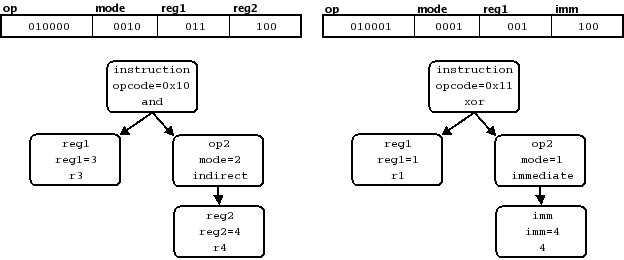
In Figure 1, “Two Encodings and the Resulting Specific Symbol Trees”, we can see the break down of two typical instructions in the example instruction set. For each instruction, we see the how the encodings split into the relevant fields and the resulting tree of specific symbols. Each node in the trees are labeled with the base family symbol, the portion of the bit pattern that matches, and then the resulting specific symbol or constructor. Notice that the use of the overlapping fields, reg2 and imm, is determined by the matching constructor for the op2 table. SLEIGH generates the disassembly and p-code for these encodings by walking the trees.
If the nodes of each tree are replaced with the display information of the corresponding specific symbol, we see how the disassembly statement is built.
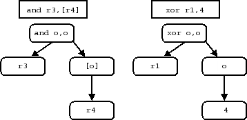
Figure 2, “Two Disassembly Trees”, shows the resulting disassembly trees corresponding to the specific symbol trees in Figure 1, “Two Encodings and the Resulting Specific Symbol Trees”. The display information comes from constructor display sections, the names of attached registers, or the integer interpretation of fields. The identifiers in a constructor display section serves as placeholders for the subtrees below them. By walking the tree, SLEIGH obtains the final illustrated assembly statements corresponding to the original instruction encodings.
A similar procedure produces the resulting p-code translation of the instruction. If each node in the specific symbol tree is replaced with the corresponding p-code, we see how the final translation is built.
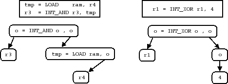
Figure 3, “Two P-code Trees” lists the final p-code translation for our example instructions and shows the trees from which the translation is derived. Symbol names within the p-code for a particular node, as with the disassembly tree, are placeholders for the subtree below them. The final translation is put together by concatenating the p-code from each node, traversing the nodes in a depth-first order. Thus the p-code of a child tends to come before the p-code of the parent node (but see Section 7.9, “P-code Macros”). Placeholders are filled in with the appropriate varnode, as determined by the export statement of the root of the corresponding subtree.
SLEIGH supports a macro facility for encapsulating semantic actions. The syntax, in effect, allows the designer to define p-code subroutines which can be invoked as part of a constructor’s semantic action. The subroutine is expanded automatically at compile time.
A macro definition is started with the macro keyword, which can occur anywhere in the file before its first use. This is followed by the global identifier for the new macro and a parameter list, comma separated and in parentheses. The body of the definition comes next, surrounded by curly braces. The body is a sequence of semantic statements with the same syntax as a constructor’s semantic section. The identifiers in the macro’s parameter list are local in scope. The macro can refer to these and any global specific symbol.
macro resultflags(op) {
  zeroflag = (op == 0);
  signflag = (op1 s< 0);
}

:add r1,r2 is opcode=0xba & r1 & r2 { r1 = r1 + r2; resultflags(r1); }
The macro is invoked in the semantic section of a constructor by using the identifier with a functional syntax, listing the varnodes which are to be passed into the macro. In the example above, the macro resultflags calculates the value of two global flags by comparing its parameter to zero. The add constructor invokes the macro so that the r1 is used in the comparisons. Parameters are passed by reference, so the value of varnodes passed into the macro can be changed. Currently, there is no syntax for returning a value from the macro, except by writing to a parameter or global symbol.
Almost any statement that can be used in a constructor can also be used in a macro. This includes assignment statements, branching statements, delayslot directives, and calls to other macros. A build directive however should not be used in a macro.
Because the nodes of a specific symbol tree are traversed in a depth-first order, the p-code for a child node in general comes before the p-code of the parent. Furthermore, without special intervention, the specification designer has no control over the order in which the children of a particular node are traversed. The build directive is used to affect these issues in the rare cases where it is necessary. The build directive occurs as another form of statement in the semantic section of a constructor. The keyword build is followed by one of the constructor’s operand identifiers. Then, instead of filling in the operand’s associated p-code based on an arbitrary traversal of the symbol tree, the directive specifies that the operand’s p-code must occur at that point in the p-code for the parent constructor.
This directive is useful in situations where an instruction supports prefixes or addressing modes with side-effects that must occur in a particular order. Suppose for example that many instructions support a condition bit in their encoding. If the bit is set, then the instruction is executed only if a status flag is set. Otherwise, the instruction always executes. This situation can be implemented by treating the instruction variations as distinct constructors. However, if many instructions support the same variation, it is probably more efficient to treat the condition bit which distinguishes the variants as a special operand.
cc: “c” is condition=1 { if (flag==1) goto inst_next; }
cc:     is condition=0 { }

:and^cc  r1,r2 is opcode=0x67 & cc & r1 & r2 {
    build cc;
    r1 = r1 & r2;
}
In this example, the conditional variant is distinguished by a ‘c’ appended to the assembly mnemonic. The cc operand performs the conditional side-effect, checking a flag in one case, or doing nothing in the other. The two forms of the instruction can now be implemented with a single constructor. To make sure that the flag is checked first, before the action of the instruction, the cc operand is forced to evaluate first with a build directive, followed by the normal action of the instruction.
For processors with a pipe-lined architecture, multiple instructions are typically executing simultaneously. This can lead to processor conventions where certain pairs of instructions do not seem to execute sequentially. The standard examples are branching instructions that execute the instruction in the delay slot. Despite the fact that execution of the branch instruction does not fall through, the following instruction is executed anyway. Such semantics can be implemented in SLEIGH with the delayslot directive.
This directive appears as a standalone statement in the semantic section of a constructor. When p- code is generated for a matching instruction, at the point where the directive occurs, p-code for the following instruction(s) will be generated and inserted. The directive takes a single integer argument, indicating the minimum number of bytes in the delay slot. Additional machine instructions will be parsed and p-code generated, until at least that many bytes have been disassembled. Typically the value of 1 is used to indicate that there is exactly one more instruction in the delay slot.
:beq r1,r2,dest is op=0xbc & r1 & r2 & dest { flag=(r1==r2);
                                              delayslot(1);
                                              if flag goto dest; }
This is an example of a conditional branching instruction with a delay slot. The p-code for the following instruction is inserted before the final CBRANCH. Notice that the delayslot directive can appear anywhere in the semantic section. In this example, the condition governing the branch is evaluated before the directive because the following instruction could conceivably affect the registers checked by the condition.
Because the delayslot directive combines two or more instructions into one, the meaning of the symbol inst_next becomes ambiguous. It is not clear anymore what exactly the “next instruction” is. SLEIGH uses the following conventions for interpreting an inst_next symbol. If it is used in the semantic section, the symbol refers to the address of the instruction after any instructions in the delay slot. However, if it is used in a disassembly action, the inst_next symbol refers to the address of the instruction immediately after the first instruction, even if there is a delay slot.